1. محصول ختم شوview
The Polibi Freestanding Buffet with Hutch is a versatile storage solution designed for dining rooms, living rooms, or kitchens. It features a classic Shaker-style design and is constructed from premium P2 grade MDF. This unit offers extensive storage options including multiple doors, drawers, shelves, and pull-out trays to help organize various household items.
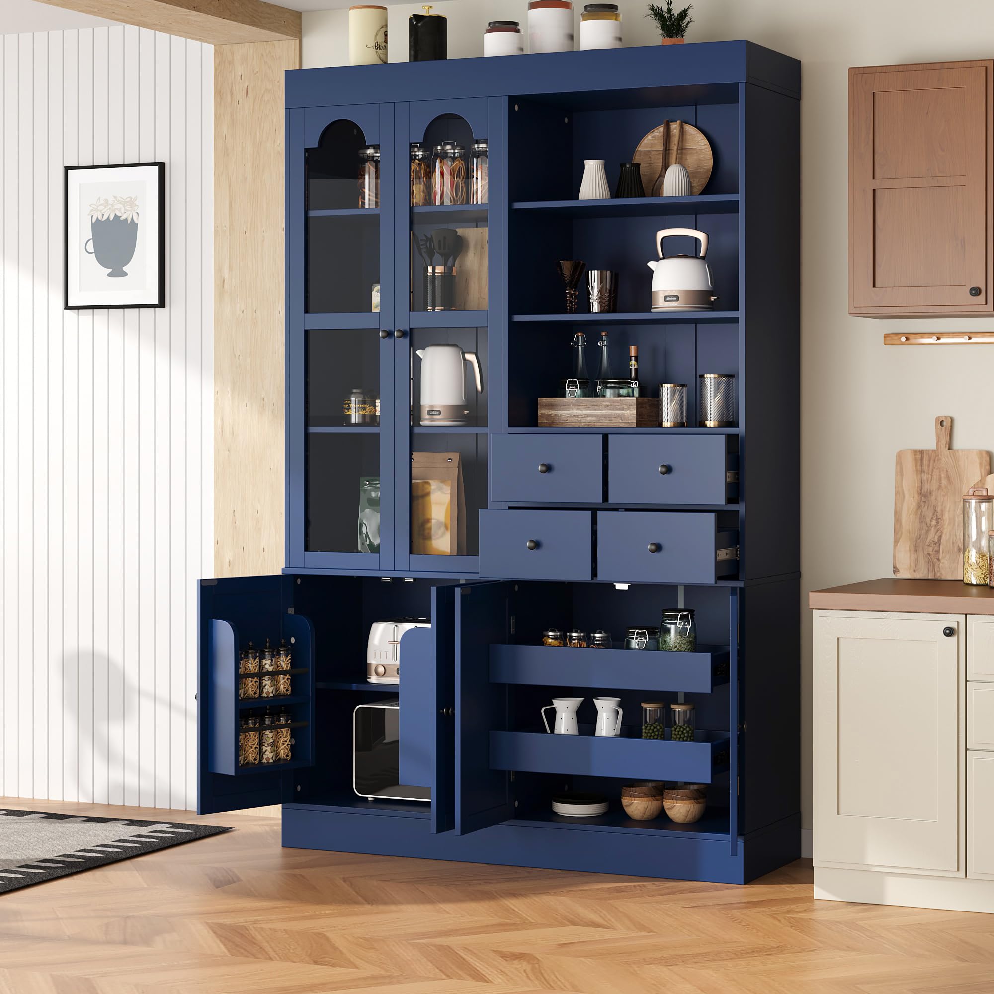
Image 1: The Polibi Freestanding Buffet with Hutch, showcasing its overall design and storage compartments.
کلیدي ځانګړتیاوې:
- Maximized & Customizable Storage: Features 6 doors (2 with tempered glass), 4 drawers, 2 pull-out trays, and 6 shelves, including a 3-level adjustable bottom shelf.
- Elegant Shaker Design: Classic style with clean lines and a sophisticated finish, crafted from premium P2 grade MDF.
- Tall & Space-Saving: Generously proportioned at 75 inches tall, providing vertical storage suitable for small to medium-sized spaces.
- Sturdy & Safe Construction: Includes tempered glass doors, reliable magnetic stoppers, and anti-tipping kits for stability.
- Ampوړتیا: Recommended capacity of 22lbs per shelf and 11lbs per drawer for efficient organization.

انځور ۳.۱: نږدې انځور view highlighting the elegant Shaker style design and premium MDF material.
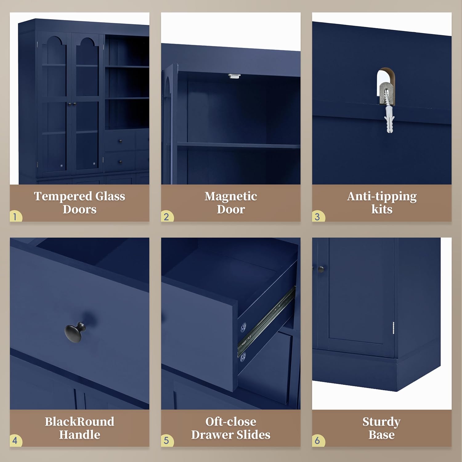
انځور ۲: تفصیلي view of key features such as tempered glass doors, magnetic door catches, anti-tipping kits, handles, drawer slides, and the sturdy base.
2. د خوندیتوب معلومات
- تل واحد په نرم او پاک سطحه راټول کړئ ترڅو د سکریچونو مخه ونیول شي.
- ډاډ ترلاسه کړئ چې ټول پیچونه او فاسټینرونه د کارولو دمخه په خوندي ډول ټینګ شوي دي.
- Do not overload shelves or drawers beyond their recommended weight capacity (22lbs per shelf, 11lbs per drawer).
- Use the provided anti-tipping kit to secure the cabinet to a wall, especially in homes with children or pets.
- د ساه بندېدو د خطرونو د مخنیوي لپاره کوچني پرزې او هارډویر له ماشومانو لرې وساتئ.
- د نصبولو خوندیتوب او اسانتیا ډاډمن کولو لپاره د دوو کسانو د راټولولو سپارښتنه کیږي.
- په دوره یي ډول ټولې اړیکې وګورئ ترڅو ډاډ ترلاسه شي چې دوی کلک پاتې دي.

Image 4: Illustration of the anti-tipping kit installation for enhanced stability and safety.
3. د بسته محتويات
Before beginning assembly, ensure all parts and hardware are present and accounted for. Refer to the included parts list in your physical manual for exact quantities and identification. The assembly video below provides a visual overview د اجزاوو.
Video 1: Assembly instructions for the Polibi Freestanding Buffet with Hutch. This video demonstrates the step-by-step process of putting the cabinet together, including identifying parts and fastening components.
4. د مجلس لارښوونې
Follow these steps carefully for proper assembly. It is recommended to have a second person assist with the assembly process.
Step 1: Prepare Base Frame Components
Attach the specified screws (A) to the base panels as shown in the diagram. Ensure they are firmly in place.

Image 5: Visual guide for Step 1, showing the initial attachment of screws to the base frame components.
2 ګام: د بنسټ چوکاټ راټول کړئ
Connect the prepared base panels using dowels (B) and cam locks (C). Tighten the cam locks to secure the frame.

Image 6: Visual guide for Step 2, demonstrating the connection of base frame panels.
Step 3: Attach Bottom Panel to Base Frame
Align the bottom panel with the assembled base frame, ensuring all dowels and cam locks are correctly positioned. Secure the panel by tightening the cam locks.

Image 7: Visual guide for Step 3, showing the attachment of the bottom panel to the base frame.
Step 4: Install Drawer Supports
Attach the drawer support blocks (G) to the designated panels using dowels (B) and screws (A). These supports will hold the drawer slides.

Image 8: Visual guide for Step 4, illustrating the installation of drawer support blocks.
Step 5: Attach Drawer Slides to Supports
Separate the drawer slides (K) and attach the outer part to the previously installed support blocks using screws (E). Ensure the slides are oriented correctly.

Image 9: Visual guide for Step 5, showing how to attach the drawer slides to the support blocks.
Step 6: Assemble Lower Cabinet Sections
Connect the side panels and back panels to form the lower cabinet sections. Use dowels (B) and cam locks (C) for secure assembly. Insert back panel strips (11) into grooves.

Image 10: Visual guide for Step 6, demonstrating the assembly of the lower cabinet sections.
Step 7: Prepare Top Panel for Lower Cabinet
Attach magnetic catches (13) and screws (A) to the top panel of the lower cabinet. These will secure the doors later.

Image 11: Visual guide for Step 7, showing the preparation of the top panel with magnetic catches.
Step 8: Prepare Side Panels for Upper Hutch
Attach screws (A) to the side panels of the upper hutch. These panels will form the outer structure of the hutch.

Image 12: Visual guide for Step 8, showing the preparation of the upper hutch side panels.
Step 9: Prepare Top Panel for Upper Hutch
Attach magnetic catches (35) and screws (A) to the top panel of the upper hutch. This panel will be the very top of the entire unit.

Image 13: Visual guide for Step 9, showing the preparation of the top panel for the upper hutch.
Step 10: Assemble Upper Hutch Base Frame
Connect the base panels (31, 32) for the upper hutch using dowels (B) and cam locks (C). This forms the bottom structure of the hutch.

Image 14: Visual guide for Step 10, demonstrating the assembly of the upper hutch's base frame.
Step 11: Attach Side Panels to Upper Hutch Base
Attach the side panels (31, 32) to the assembled upper hutch base using dowels (B) and cam locks (C). Ensure a snug fit.

Image 15: Visual guide for Step 11, showing the attachment of side panels to the upper hutch base.
Step 12: Install Drawer Slides for Upper Hutch
Attach the drawer slides (D1) to the designated panels (20, 21) of the upper hutch using screws (A) and (E). These slides are for the smaller drawers in the hutch section.

Image 16: Visual guide for Step 12, demonstrating the installation of drawer slides for the upper hutch.
Step 13: Assemble Small Drawer Sides
Attach the remaining drawer slides (D1) to the small side panels (22) using screws (A) and (E). These will form the sides of the small drawers.

Image 17: Visual guide for Step 13, showing the assembly of small drawer sides with slides.
Step 14: Assemble Small Drawer Fronts
Connect the small drawer front panels (25) to the side panels using dowels (B) and cam locks (C). Secure with screws (A).

Image 18: Visual guide for Step 14, demonstrating the assembly of small drawer fronts.
Step 15: Assemble Upper Hutch Internal Shelves
Connect the internal shelves (23, 24) to the side panels of the upper hutch using dowels (B) and cam locks (C). Secure with screws (F).

Image 19: Visual guide for Step 15, showing the assembly of internal shelves for the upper hutch.
Step 16: Assemble Upper Hutch Back Panels
Attach the back panels (26, 46) to the upper hutch structure using dowels (B) and cam locks (C). Secure with screws (F).

Image 20: Visual guide for Step 16, demonstrating the assembly of back panels for the upper hutch.
Step 17: Attach Top Panel to Upper Hutch
Secure the top panel (from Step 9) to the assembled upper hutch structure using dowels (B) and cam locks (C).

Image 21: Visual guide for Step 17, showing the attachment of the top panel to the upper hutch.
Step 18: Attach Back Panels to Lower Cabinet
Attach the back panels (27, 28) to the lower cabinet structure using dowels (B) and cam locks (C). Ensure they fit into the grooves.

Image 22: Visual guide for Step 18, demonstrating the attachment of back panels to the lower cabinet.
Step 19: Attach Top Panel to Lower Cabinet
Secure the top panel (from Step 7) to the assembled lower cabinet structure using dowels (B) and cam locks (C).

Image 23: Visual guide for Step 19, showing the attachment of the top panel to the lower cabinet.
Step 20: Install Shelf Pins
Insert shelf pins (P) into the pre-drilled holes inside the cabinet sections at your desired height. These will support the adjustable shelves.

Image 24: Visual guide for Step 20, demonstrating the installation of shelf pins.
Step 21: Assemble Pull-Out Trays (Part 1)
Attach screws (A) and dowels (F) to the side panels (16, 17) of the pull-out trays. Connect these to the front and back panels (18) using cam locks (C).

Image 25: Visual guide for Step 21, showing the initial assembly of the pull-out trays.
Step 22: Assemble Pull-Out Trays (Part 2)
Insert the metal rods (19) into the pre-drilled holes in the side panels of the pull-out trays. Secure with screws (R).

Image 26: Visual guide for Step 22, showing the completion of the pull-out tray assembly.
Step 23: Attach Hinges and Knobs to Lower Doors
Attach hinges (J) to the lower cabinet doors (14, 15) using screws (A) and (M). Install the door knobs (I) as shown.

Image 27: Visual guide for Step 23, demonstrating the attachment of hinges and knobs to the lower doors.
Step 24: Attach Hinges and Knobs to Upper Glass Doors
Attach hinges (J) to the upper glass doors (47, 48) using screws (M). Install the door knobs (I) as shown.

Image 28: Visual guide for Step 24, showing the attachment of hinges and knobs to the upper glass doors.
Step 25: Install Adjustable Shelves
Place the adjustable shelves (9) onto the installed shelf pins (P) inside the cabinet sections. Adjust height as needed.

Image 29: Visual guide for Step 25, demonstrating the installation of adjustable shelves.
Step 26: Assemble Drawer Boxes (Part 1)
Attach screws (A) to the side panels (41, 42) of the drawer boxes. Connect these to the front and back panels (43, 44) using dowels (H) and cam locks (C). Attach the inner part of the drawer slides (E) to the side panels.

Image 30: Visual guide for Step 26, showing the initial assembly of the drawer boxes.
Step 27-29: Assemble Drawer Boxes (Part 2)
Continue assembling the drawer boxes by attaching the bottom panel (36, 37, 38, 40) and securing all sides with screws (A), dowels (H), and cam locks (C). Attach the drawer knobs (I) to the front panels.

Image 31: Visual guide for Steps 27-29, demonstrating the completion of the drawer box assembly.
Step 30: Insert Drawers and Pull-Out Trays
Carefully slide the assembled drawers and pull-out trays into their respective slots in the cabinet. Ensure they glide smoothly.

Image 32: Visual guide for Step 30, showing the insertion of drawers and pull-out trays.
Step 31: Attach Lower Doors to Cabinet
Attach the lower doors (from Step 23) to the cabinet by securing the hinges to the cabinet frame using screws (J).

Image 33: Visual guide for Step 31, demonstrating the attachment of lower doors.
Step 32: Install Door Shelves
Attach the door shelves to the inside of the lower cabinet doors using screws (F) and cam locks (C). These provide additional storage.

Image 34: Visual guide for Step 32, showing the installation of door shelves.
Step 33: Attach Upper Glass Doors to Hutch
Attach the upper glass doors (from Step 24) to the hutch by securing the hinges to the hutch frame using screws (J). Install the door knobs (I).

Image 35: Visual guide for Step 33, demonstrating the attachment of upper glass doors.
Step 34: Install Anti-Tipping Kit
Secure the anti-tipping brackets (N) to the top rear of the cabinet and to the wall using appropriate wall anchors and screws. This is a crucial safety step.

Image 36: Visual guide for Step 34, showing the installation of the anti-tipping kit.
5. عملیاتي لارښوونې
Using Doors and Drawers:
- Gently open and close doors and drawers using the provided handles.
- Avoid slamming to prevent damage to hinges and slides.
- The magnetic stoppers ensure doors remain securely closed.
د الماریو تنظیمول:
- To adjust shelf height, remove items from the shelf.
- Carefully lift the shelf and remove the shelf pins.
- Reinsert the pins into the desired holes and place the shelf back on top.
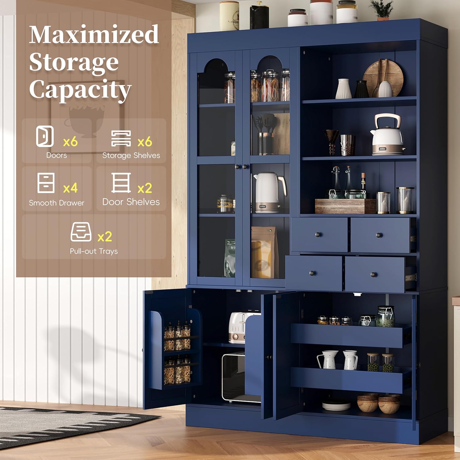
Image 37: The cabinet interior demonstrating maximized storage capacity with doors, shelves, drawers, and pull-out trays.
6. پاملرنه او ساتنه
- پاکول: سطحونه په نرمۍ سره مسح کړئ، دamp ټوکر. د سختو کیمیاوي موادو یا خړوبونکو پاکوونکو څخه ډډه وکړئ چې ممکن پای ته زیان ورسوي.
- څاڅکي: د رنګ کولو یا د اوبو د زیان څخه د مخنیوي لپاره توی شوي مواد سمدلاسه پاک کړئ.
- د لمر وړانګې: د لمر د مستقیم لمر وړانګو ته د اوږدې مودې تماس څخه ډډه وکړئ ترڅو د لمر د وړانګو مخه ونیسئ.
- تودوخه: ګرم توکي په مستقیم ډول په سطحه مه کېږدئ. د کوسټرونو یا محافظتي پیډونو څخه کار واخلئ.
- رطوبت: په خونه کې د رطوبت یو ثابت کچه وساتئ ترڅو د لرګیو د مسخ کیدو یا درزیدو مخه ونیسئ.
- هارډویر: Periodically check all screws and fasteners and tighten them if necessary to ensure stability.
7. ستونزه حل کول
عام مسایل او حل لارې:
| ستونزه | احتمالي لامل | د حل لاره |
|---|---|---|
| کابینه ټکان ورکوونکې یا بې ثباته احساسوي. | خلاص بندونه؛ نا مساوي فرش؛ د ټیپ کولو ضد کټ نه دی نصب شوی. | Tighten all screws and cam locks. Ensure the cabinet is on a level surface. Install the anti-tipping kit as per instructions. |
| درازونه په اسانۍ سره نه ښویېږي. | Drawer slides misaligned or damaged; debris in slides. | Check alignment of drawer slides and ensure they are securely attached. Clean any debris from the tracks. |
| دروازې په سمه توګه نه تړل کېږي. | قبضې په غلط ډول تنظیم شوي دي؛ مقناطیسي کیچ ښکیل نه دی. | Adjust hinges to ensure proper alignment. Check if magnetic catches are securely installed and functioning. |
| د غونډې پرمهال ورکې برخې. | د بسته بندۍ تېروتنه. | Contact Polibi customer support with your purchase details and the specific missing parts. |
8. مشخصات
| فیچر | تفصیل |
|---|---|
| برانډ | polybi |
| رنګ | آبي |
| د محصول ابعاد | ۱۶"د x ۲۶"وچ x ۴۷"ح |
| ځانګړي ځانګړتیاوې | 4 Drawers, Door Shelves, Glass Doors, Pull-Out Trays |
| د نصب کولو ډول | فریسټینډینګ |
| د کوټې ډول | Dining Room, Living Room |
| د دروازې سټایل | Hinge-door |
| د توکي وزن | 191.4 پونډه |
| مجلس ته اړتیا ده | هو |
| مواد | P2 Grade MDF |

Image 38: Technical drawing showing the detailed dimensions of the buffet with hutch.
9. تضمین او ملاتړ
For warranty information, product support, or to order replacement parts, please contact Polibi customer service. Refer to your purchase documentation for specific warranty terms and contact details.
- د پیرودونکو خدمت: Please refer to the contact information provided with your product packaging or on the Polibi official webسایټ
- د ساتنې پلانونه: د پیرودلو لپاره اختیاري دوه کلن او درې کلن محافظتي پلانونه شتون لري.
- راستنیدنه: This product typically has a 30-day return policy for refund or replacement.


